Portable Impulse Voltage Test System
Portable Impulse Voltage Test System
Highlights :
- Computerized control system with user friendly software.
- Integrated software solution for data evaluation.
- Easy & quick reconfiguration to meet different testing requirements.
- Reliable, accurate and fail - safe triggering circuitry.
- Low internal inductance ensures high efficiency.
- Alarm annunciation to display all fault conditions
- Equipped with wave shaping resistors for performing full lightning, switching and Chopped impulse wave tests on a wide range of loads.
reserves the right to make changes to specifications of products described at any time without notice and without obligation to notify any person of such changes.
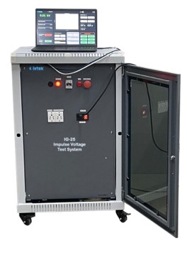
IG-25 Impulse voltage test systems are designed to generate impulse voltages that simulate lightning strikes and switching surges up to 25 kV in both polarities. The waveform generated has a rise rime of 1.2 μS and 50 μS duration. This test is described in various standards including IEC 61000-4-5, IEC61180, IS 60898:1and IS 12640 etc.
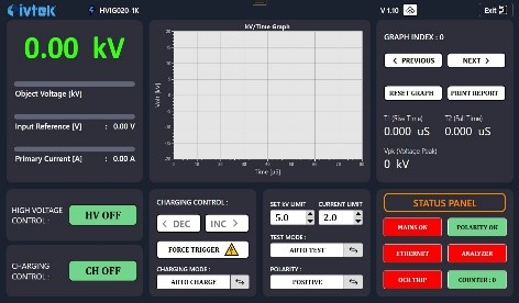
The user-friendly laptop based digital control unit allows impulse testing in manual mode and fully automatic mode. Higher efficiency is ensured due to very low internal inductance. The enclosed sphere gaps significantly reduces the effect of environmental conditions thus minimizing misfires.
The IG-25 impulse voltage generator is mounted on a mobile base frame equipped with and moved by wheels. The spark gap distance is moved linearly in function of the pre-selected charging voltage. The stages have been designed for a very low inductance. This allows to test a large load range.
The adaptation to different test objects (different loads) can be done by using different front and tail resistors. Generator has internal front resistors and additionally at the final output external front resistor is provided which connects impulse generator and test object. The external front resistor is equipped with taps. By selecting different taps, the generated wave shape can be adjusted quickly and easily.
The impulse generator is equipped with a blower and an air filter. This blower injects air with a slight over pressure inside the spark gap encapsulation of the generator. This avoids dust accumulation inside the encapsulation. The encapsulation also damps the noise produced by the arcs and protects the operating personnel from U.V. radiations.
The integrated safety grounding system consists of two earthing switches which discharge the impulse capacitors via earthing resistors. Additionally, a motorized grounding band creates a short circuit across all capacitors and grounds all stages.
The earthing system is completed with a fiberglass earth rod with hook, equipped with earth wire as well as with low inductive copper foil.
TECHNICAL SPECIFICATIONS :
| Max. Voltage Rating | 20 kV |
| Least Count | 0.01 kV |
| Energy Rating | 200 J -2kJ |
| Wave Parameter | LI : 1.2 μS / 50 μS |
| Tolerance | Upeak : ± 5% , T1 : ± 30% T2 : ± 20% |
| Surge Impedance | 500Ω |
| Impulse Duty Cycle | > 70% of Rated Voltage - Intermittent < 70% of Rated Voltage - Continuous |
MEASURING & ANALYZING SYSTEM :
| Number of Channels | Two (Independent) |
| Over Voltage Protection | 2 kV |
| Input Impedance | 1 M, 14 pF |
| Sampling Rate | 200 MS/s max. |
| Accuracy | ± 1% for Upeak ± 2% for T1, T2 |
| Operating temp. | -10 0C to + 50 0C |
| Storage temp. | > -10 0C to + 60 0C |
| Relative humidity | < 95 %, non-condensing |
| Supply Voltage | 230 Vac ± 10%, 50 Hz ± 5% |
| Safety/Protection | Safety interlocks, over-voltage, over-current, auto restore etc. |
ACCESSORIES
Laptop with control and analyzing software, Power Cord, Earthing Rod, Instruction Manual & Calibration Certificate.